- Deriving Equation 4: d=V2Δt-½aΔt²
Well, equation 4 is sort of different from equation 3 but they do share some same components, such as the triangle part. However, the rectangular part is the major difference. The purpose of equation 4 is to utilizes a larger rectangle to subtract the triangular part to find the trapezoid area.
In this equation, we can find out the area of the larger rectangle by substituting V2 as the height. So the equation would look like: d=V2Δt.
Finally, you need to subtract the triangular value from the value of the large rectangle to form the trapezoid. So the final equation looks like this:
d=V2Δt-½aΔt² ; D
Friday, October 22, 2010

Deriving Equation 3
- Deriving Equation 3: d=V1Δt + ½aΔt²
Our goal in this equation is to find the displacement. We can do that by finding the area of the trapezoid made by the slope and the x axis. The equation basically divided the area of the trapezoid into two parts: a triangle and a rectangle.
The formula for the area of a triangle is A= bh/2. If we apply to that equation for the values on the triangle on the graph, the equation would be d= (v2-v1)Δt /2. To simplify this equation, we can replace (v2-v1) with aΔt. So the new equation would look like
d=½ (aΔt )Δt
d=½ aΔt²
and there we have the second part of equation 3 and now we have to derive the rectangular part.
The formula for the area of a rectangle is A=lw. If we apply to that equation for the values on the rectangle on the graph, the equation would be d= v1(t2-t1). We can simplify this equation further by replacing (t2-t1) with Δt.
d=V1Δt and here we have the first part of equation 3.
Finally, we combine the two equations together and the result is d=V1Δt + ½aΔt² - equation 3. : )
Our goal in this equation is to find the displacement. We can do that by finding the area of the trapezoid made by the slope and the x axis. The equation basically divided the area of the trapezoid into two parts: a triangle and a rectangle.
The formula for the area of a triangle is A= bh/2. If we apply to that equation for the values on the triangle on the graph, the equation would be d= (v2-v1)Δt /2. To simplify this equation, we can replace (v2-v1) with aΔt. So the new equation would look like
d=½ (aΔt )Δt
d=½ aΔt²
and there we have the second part of equation 3 and now we have to derive the rectangular part.
The formula for the area of a rectangle is A=lw. If we apply to that equation for the values on the rectangle on the graph, the equation would be d= v1(t2-t1). We can simplify this equation further by replacing (t2-t1) with Δt.
d=V1Δt and here we have the first part of equation 3.
Finally, we combine the two equations together and the result is d=V1Δt + ½aΔt² - equation 3. : )
Wednesday, October 20, 2010
Translating Graphs Thingys
Graph 1
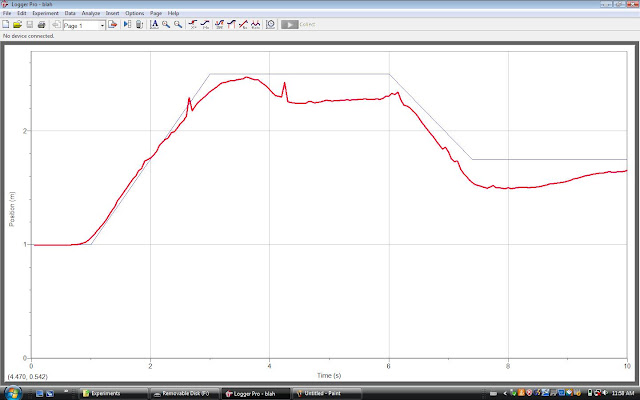 We 80 cm from the motion detector. We walked @ a constant speed... ok... tried to walk away @ a constant speed and we stopped. Then, we walked forward and stopped the rest of the graph.
Graph 2
 k for this one, we started @ 3 m, we walked towards the motion detector for @ a constant speed for 3 secs and we stopped.@ 4 secs we continued to walk away and stopped @ 5 secs. Finally, we walked away from the motion detector @ a constant speed until 10 secs.
Graph 3
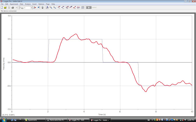
This is a velocity/time graph and it is probably one of the hardest to walk. From 0 to 2 secs, our motion was still. From 2 secs to 5 secs, we were @ a constant velocity of 0.5 m/s. From 5 to 7, our motion was still again. Finally, from 7 to 10 secs, we walked @ a constant velocity of -0.5 m/s.
Graph 4
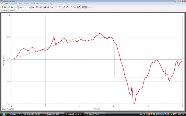
Just when i thought it graph 3 was the hardest one to walk... here comes graph 4. I gotta say... this is the worst result we got in this experiment. Graph 4 is also a velocity/time graph. In the first 4 secs, the velocity increase constantly to 0.5 m/s. From 4 secs to 6 secs, the velocity 0.5 m/s. From 6 secs to 9 secs, the velocity, is about -0.4. @ 9 - 10 secs, our motion was still.
Graph 5

Graph 5 is a distance time graph. From start to about 3.5 secs, we moved away from the motion detector @ a constant speed. Then we stood still and started moving further away from the motion detector @ about 6.3 secs.
Graph 6
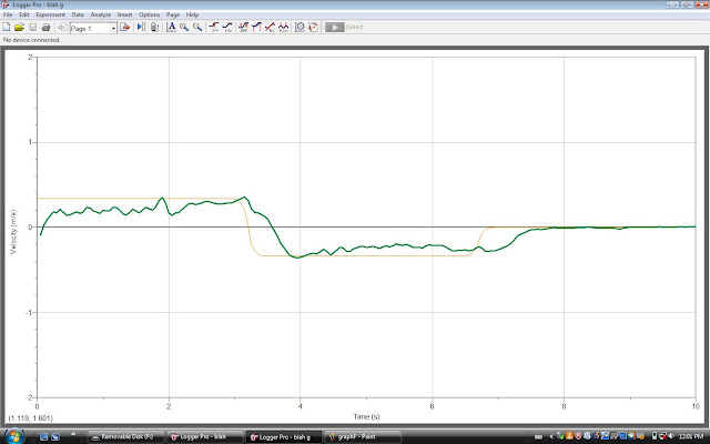
Graph 6 is another velocity/time graph. We moved @ a constant speed of about 0.2 m/s for the first 3 secs.
Then from 3 secs to 6.2 secs, our velocity was about - 0.4. For the rest of the graph, our motion was still.

Graph 2

Graph 3
This is a velocity/time graph and it is probably one of the hardest to walk. From 0 to 2 secs, our motion was still. From 2 secs to 5 secs, we were @ a constant velocity of 0.5 m/s. From 5 to 7, our motion was still again. Finally, from 7 to 10 secs, we walked @ a constant velocity of -0.5 m/s.
Graph 4
Just when i thought it graph 3 was the hardest one to walk... here comes graph 4. I gotta say... this is the worst result we got in this experiment. Graph 4 is also a velocity/time graph. In the first 4 secs, the velocity increase constantly to 0.5 m/s. From 4 secs to 6 secs, the velocity 0.5 m/s. From 6 secs to 9 secs, the velocity, is about -0.4. @ 9 - 10 secs, our motion was still.
Graph 5

Graph 5 is a distance time graph. From start to about 3.5 secs, we moved away from the motion detector @ a constant speed. Then we stood still and started moving further away from the motion detector @ about 6.3 secs.
Graph 6
Graph 6 is another velocity/time graph. We moved @ a constant speed of about 0.2 m/s for the first 3 secs.
Then from 3 secs to 6.2 secs, our velocity was about - 0.4. For the rest of the graph, our motion was still.
Thursday, September 30, 2010
MOTOR assignment~!
Today in physics class, we had a challenge of building a functioning motor which is able to spin 2 cycles. my partner Keven and I had brought materials such as a wooden base, a kabob stick, 4 nails, a cork and some copper wires. Then as soon as the period start, both of us got right to work.
 Here is Kevin hard @ work... i actually dun hav a pic of me doing
work... but i did do work 2 lol
After about 50 minutes of hard work, this is wat our final product looks like...
 I know... shes beautiful...
 Woooow... is Kevin really tat much taller than me?!

And finally our result...
Today in physics class, we had a challenge of building a functioning motor which is able to spin 2 cycles. my partner Keven and I had brought materials such as a wooden base, a kabob stick, 4 nails, a cork and some copper wires. Then as soon as the period start, both of us got right to work.
work... but i did do work 2 lol
After about 50 minutes of hard work, this is wat our final product looks like...
And finally our result...
If ur too lazy to watch the vid.... it worked
In conclusion, we successfully built a motor and i reallyyyy enjoyed the challenge... hope tat theres more fun projects like one this in the future.
Wednesday, September 22, 2010
Notes on magnetics
1. A magnetic field is a region which attracts magnetic forces.
2.There are two different forces, which are north and south.
3. We can use a test compass to find out the direction in which the north seeking pole of this compass would point at the point in space.
4. The metals that attracts magnetic forces are called ferromagnetic metals. All magnets are made of ferromagentics.
5. Domain theory of magnets Domain theory of magnets states all large magnets is made up of many smaller rotating magnets called dipoles. If dipoles line up, a magnetic domain is produced.
6. Right hand rules is a way to determine how magnetic forces is functioning. There are three right hand rules in total.
7. Oersted's principle states that change moving through a conductor produces a circular magnetic field around the conductor.
8. Right hand rule # 1 is used for conventional current flow. See image for instructions
 9. The second right hand rule is used for coils. See image for instructions

10. The strength of a magnet can be adjusted by using the opposite magnetic field (B).
2.There are two different forces, which are north and south.
3. We can use a test compass to find out the direction in which the north seeking pole of this compass would point at the point in space.
4. The metals that attracts magnetic forces are called ferromagnetic metals. All magnets are made of ferromagentics.
5. Domain theory of magnets Domain theory of magnets states all large magnets is made up of many smaller rotating magnets called dipoles. If dipoles line up, a magnetic domain is produced.
6. Right hand rules is a way to determine how magnetic forces is functioning. There are three right hand rules in total.
7. Oersted's principle states that change moving through a conductor produces a circular magnetic field around the conductor.
8. Right hand rule # 1 is used for conventional current flow. See image for instructions


10. The strength of a magnet can be adjusted by using the opposite magnetic field (B).
Wednesday, September 15, 2010
Notes on Resistance, Ohm's law
 Through the past two weeks of blogging, i found a major problem with this thing... I CAN'T UPLOAD ANY PICS~~~~! But just yesterday, i discovered from Young tat I've been writing in HTML mode. DD : Anyways, here's my notes, WITH SOME PICS.
 1) Current flow depends on 2 two major factors: the potential difference of the power supply and the nature of the pathway through the loads that are using the electric potential energy.
 2) Resistance is the hindrance to the flow of charge.
3) We can calculate resistance by using the following formula: R (Resistance) = V (Voltage) / I (Current)
4) Ohm's law is the ratio of Voltage over Current. As we found out with our lab, as the current increase, so does potential difference. Vise versa, if the current decreases, so will the potential difference.
5) Factors that can determine the resistance of a conductor would be the likes of length, crossed-sectional area, material it is made of and its temperature.
 6) The gauge # of a wire
 signals its crossed section area.
7) In a series circuit, the loads are connected one after another in a SINGLE path. In parallel circuits, they are side by side.
8) Kirchhoff's current law: the total amount of current into a junction point of a circuit equals the total current that flows out of the same junction. This law can be represented by the following equation: I1+I2+I3=IT=I4=I5
9) Kirchhoff's Voltage law: the total of all electrical potential decreases in any complete circuit loop is equal to any potential increases in that circuit loop. This law can be represented by the following equation: VT=V1+V2+V3
10) Laws of conservation of electric charge and the conservation of energy states that in any circuit, there is no net gain or loss of electrical charge or energy.
Subscribe to:
Posts (Atom)